wastewater line Innichen - Sexten

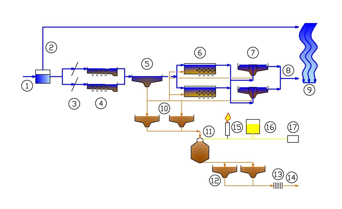
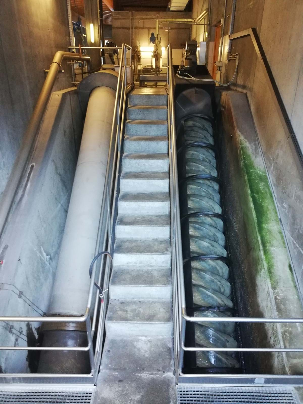
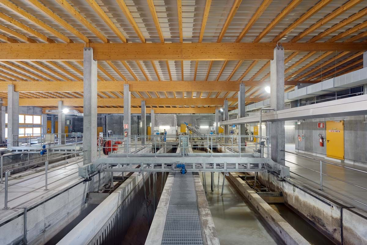
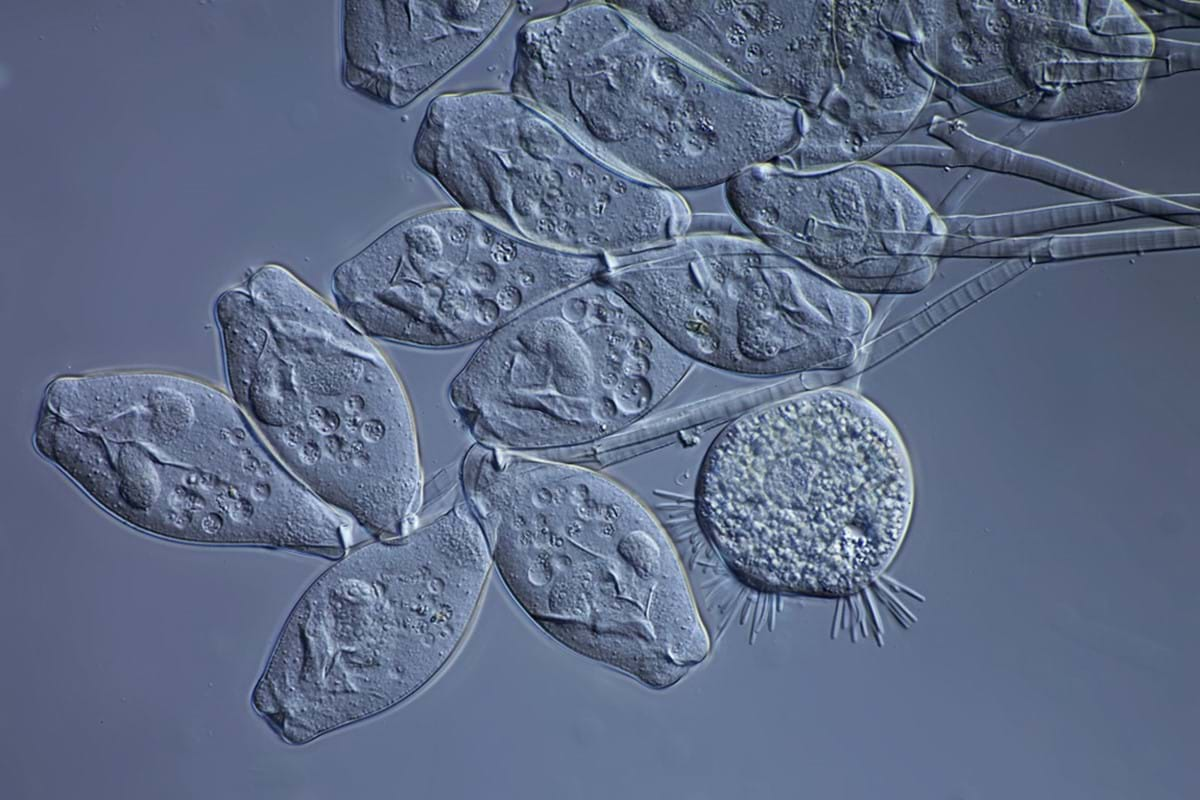
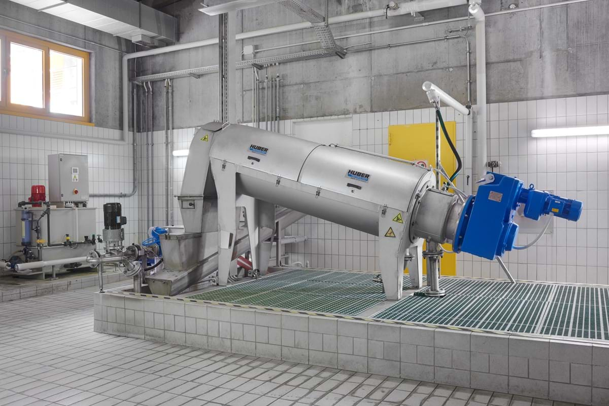
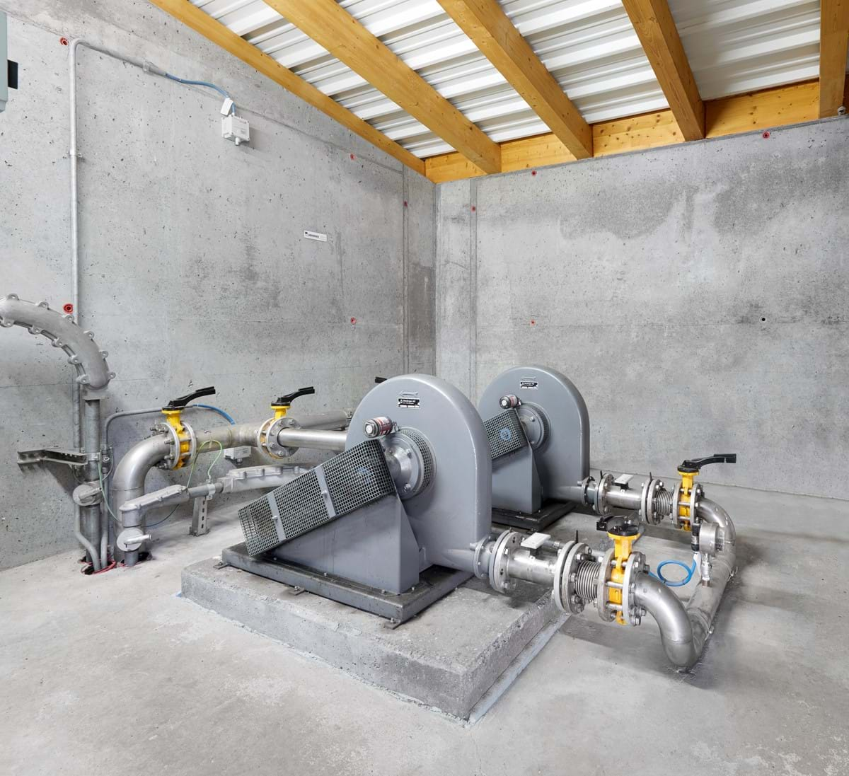
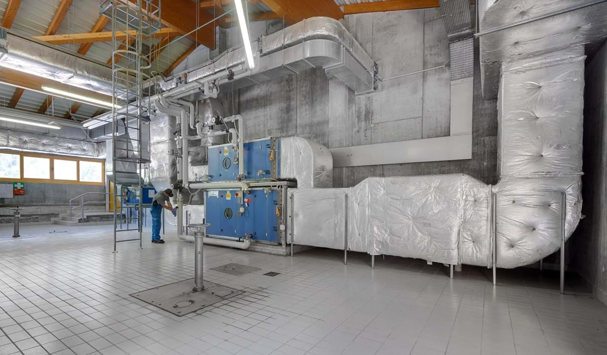
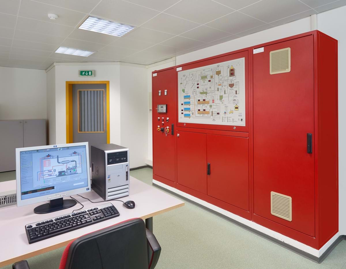
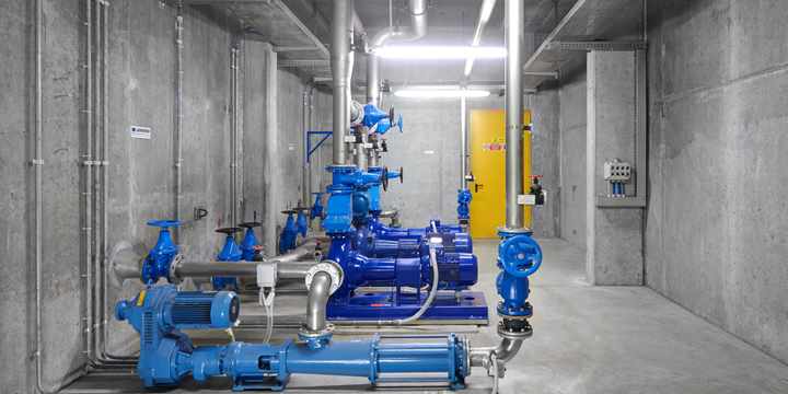
Wastewater treatment process

The sewage treatment plant was dimensioned for a capacity of approx. 36,000 inhabitants from the residential population, tourism, industry and commerce and was designed and planned to treat the wastewater according to the highest requirements, i.e. on the organic pollution load as well as on the high-grade reduction of nitrogen and phosphorus compounds.

The goal of wastewater treatment is achieved with physical, biological, biomechanical and chemical process steps.

Legend Function diagram

Water sludge Gas
     
1) inflow 11) Pre-thickener 16) gas accumulator
2) rain relief 12) Digestion chamber 17) gas torch
3) pumping station 13) Post thickeners 18) gas utilisation
4) screening plant 14) sludge press  
5) Aerated grit chamber 15) sludge disposal  
6) Preliminary clarifier    
7) Biological basin    
8) Final clarifier:    
9) drain    
10) Drau River    

Inlet channel and pumping station

The waste water is fed to the sewage treatment plant via the sewer system. There the wastewater must be lifted via two pipe screws [3, functional diagram] so that the water can then pass through the plant in free fall.

Inlet channel and pumping station

lifting screws

Mechanical cleaning

The mechanical sewage, with a 25% organic load reduction efficiency, is assured by a spire screen[4], by aerated grit chamber [5], bar-screens and primary clarifier [6].

Mechanical cleaning

Aerated grit chamber

Biological cleaning

After that, the sewage treated mechanically cross a series of 3 falls [7]: in the first one, in totally oxygen absence, takes place the bio-chemical process of partial phosphoric compounds deleting, in the second one, the nitrous compounds reduction is realized (denitrification) while in the last one, the bigger one, atmospheric oxygen is injected to permit la biodegradation of organic compounds and nitrous compounds oxidation (nitrification). The recycle of vented sewage, of actives sludges and the regulation of oxygen concentration, permit the creation of an ambient in which microorganisms and various nature batteries may easily do the proper work of degradation of pollutant load. These microorganisms, in bow structures, are the actives sludges that are separated by sedimentation in the big secondary clarifier [8]. The last reduction of phosphoric compounds is obtained by simultaneous precipitation (adding chemicals agents).

Biological cleaning

Activated sludge under the microscope

final clarification

The water’s superior layer, now purified, flows out on toothed threshold [8], is analyzed by a measurement and metering station ( for quality and flow rate), and flows out into Drau River [10].

final clarification

The clarifiers

The sludge treatment

The sludge coming from the first clarifiers [6] (primary sludge) is thickened mechanically by a pre-thickener. The sludge is now eliminated from secondary clarifiers and thickened mechanically by screencloth. The pre-thickened sludges are now reached at a temperature of 38°C approx and digested into an anaerobic digestion chamber [12]. The sludges, now stabilized and neutrals, are dried with a screw press [14].

The sludge treatment

the screw press

Gas line

During the digestion process [12], the microorganisms transforming the organic compounds on CO2 and methane with high energetic content, available for thermal heating of digestion chambers and for factory heating. To take a solution at the gas over production, in the Innichen - Sexten - plant is provided a storage gas tank [16].

The gas line is composed by: gasometer [16], pressurization station, gas flare [17], 2 heaters and 1 cogeneration groups [18].

Gas line

gas booster station

Ventilation system

During Innichen-Sexten plant engineer studies, a special importance matter was the particular attention at stinks emissions monitoring. All the stronger sources and ways of stinkness (fine bar screen, aerated grift chamber, clarifier and the entire sewerage treatment plant) are positioned on warehouses with the proper air purification system.
The stink air, until a flow rate of 15.000 m³/h, is purified with scrubber at crossing flows system with, storing the thermal energy produced.

Ventilation system

proper air purification system

Components and power

For sewerage system and sludges treatment were provided a total amount of 109 units divided into instrumentation, machineries, for a total amount of power consumption of approx 300 kW; the same items quantity were necessary for heating system, ventilation, air treatment, lightness systems, hydro feed exc. For power
plant, control and regulation of all these plants and systems, 25 km of bundles and cables were provided.

Components and power

The control centre of the plant